

Solar PV is scaling quickly, but every installation still depends on small electrical decisions. IRENA’s Renewable Capacity Statistics 2024 reports that solar power added approximately 346 GW worldwide in 2023. That growth places more pressure on component selection, especially where multiple strings meet. A poorly specified Solar Combiner can create heat, nuisance trips, difficult maintenance, or unsafe isolation. The cabinet may look simple. Its internal details are not.
This guide presents seven practical Solar Combiner buying tips for installers, engineers, and project owners. We will examine current ratings, fuse coordination, enclosure protection, monitoring, surge protection, wiring space, and certification evidence. Bill Brooks, PE, a respected photovoltaic electrical engineer, has warned, “The PV system is only as good as its weakest component.” His point deserves attention. A combiner should not be chosen only by string count or purchase price. Check the datasheet against the actual array voltage, current, ambient temperature, cable size, and fault conditions. IEA’s Renewables 2024 report expects solar PV to remain the dominant source of new renewable capacity through 2030, making these checks increasingly important. Still, no checklist replaces field judgment. Specifications can be incomplete. Installation assumptions can be wrong. That is why a careful buyer should question every unclear rating before signing an order.
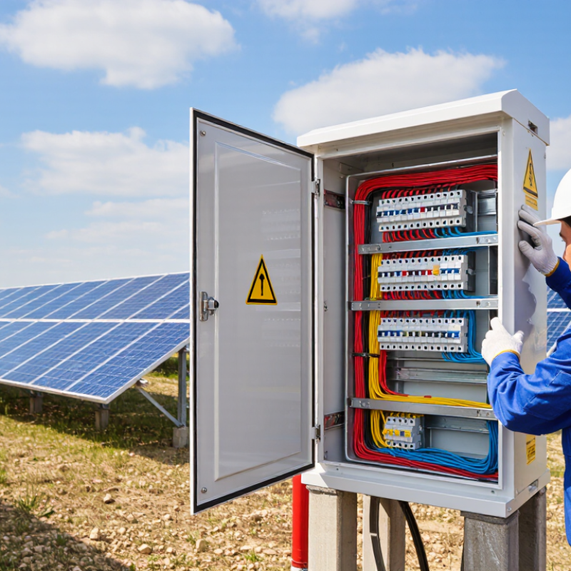
A solar combiner joins several photovoltaic string circuits before they reach the inverter. It reduces cable runs and keeps string protection in one accessible enclosure. In field inspections, this arrangement makes fault tracing easier, especially when labels remain clear and dry.
Before buying, check seven practical details. Check the rated voltage and current against the array, not only today’s output. Check the number of string inputs and leave limited room for future expansion. Check whether each input has suitable fuses or circuit protection. Check the enclosure’s weather resistance for its installation location. Check internal spacing and terminal quality, because heat often begins at poor connections. Check grounding and surge protection provisions. Check certification documents and installation instructions from a verifiable source.
A useful combiner should also allow safe isolation and simple visual inspection. Transparent covers can help, but they do not replace proper testing. Look for clear polarity markings, firm cable glands, and terminals that match the conductor size. I once saw a compact enclosure chosen for convenience, yet its cramped wiring slowed maintenance considerably. That mistake was avoidable. Bigger is not always better, but inaccessible components create real operating costs. Ask how technicians will measure, replace, and document each protective device after installation.
A solar combiner must match the system voltage, current, and circuit capacity. Check the module open-circuit voltage first, then adjust it for the lowest expected site temperature. Cold weather can increase voltage beyond the value printed on the module label. NREL’s 2023 Photovoltaic System Cost Benchmark evaluates utility-scale designs around 1,500 Vdc, while smaller systems often use 600 or 1,000 Vdc architectures. The combiner’s maximum voltage rating must meet or exceed the calculated cold-weather voltage. A mismatch can damage insulation, fuses, or switching equipment.
Current checks require more than adding module ratings. Under common NEC PV sizing rules, short-circuit current is multiplied by 125% for design calculations. Continuous output may require another 125% adjustment for conductors and overcurrent protection. For example, a string with a 13-ampere short-circuit current may require protection based on 16.25 amperes. Then count every parallel string. The busbar, fuse holders, terminals, and enclosure must carry the resulting current without overheating. IEC 62548-1 also emphasizes proper PV array protection and switching arrangements.
Leave some practical margin. Do not guess. I have seen project sheets list the correct fuse size but overlook the combiner’s total bus capacity. The IEA PVPS Trends 2024 report recorded 456 GW of new photovoltaic capacity in 2023, showing how quickly system scale is expanding. Larger arrays make small calculation errors more costly. Recheck the design against local electrical rules, temperature records, cable lengths, and the actual number of connected circuits.
Before selecting a combiner box, compare the array voltage with the equipment rating and confirm that the current capacity covers the combined short-circuit current of all parallel strings. The examples below use a realistic 13 A short-circuit current per string and a 125% design-current factor commonly applied to continuous PV output.
Calculation: array short-circuit current = string Isc × number of parallel strings; minimum design current = array Isc × 125%. Always verify the module datasheet, maximum system voltage, fuse requirements, conductor ampacity, and applicable local electrical code.
When selecting a solar combiner, inspect enclosure protection before counting circuits or fuse positions. The IEA PVPS Trends 2024 report recorded more than 400 GW of new photovoltaic capacity in 2023. Much of this equipment operates outdoors, often for decades. IEC 60529 defines IP65 as dust-tight protection against water jets. IP66 provides stronger water-jet resistance. However, an IP rating is not a guarantee of reliable field performance.
Check the installation environment carefully. Coastal sites need corrosion-resistant materials and sealed, compatible cable glands. Desert sites demand strong UV resistance, dust control, and safe heat dissipation. In cold regions, condensation can form inside the enclosure after sunrise. Provide drainage where the design allows it. Keep the box shaded when practical, but never block ventilation or maintenance access. NEMA 250 Type 4X can support demanding outdoor conditions, yet it does not replace correct installation.
Inspect gasket compression, door alignment, grounding points, and unused cable entries. A small opening can defeat an expensive enclosure. NREL’s widely cited degradation analysis found median PV degradation near 0.5% annually, making long-term protection commercially important. I would not treat IP66 as the complete answer. Internal temperature, mounting position, salt exposure, and inspection access deserve equal attention. Field assumptions are often wrong. Test the actual site conditions before purchase.
A solar combiner should protect more than wiring; it should support safe, repeatable inspections. Check for touch-safe covers, secure cable glands, clear polarity markings, and DC-rated disconnects. Surge protection and correctly sized fuses matter, but only when matched to the system’s voltage and current. An enclosure with a high ingress-protection rating is useful in dusty or wet locations. Still, a strong rating cannot fix poor installation.
Tip 1: Ask for current certification documents. Look for standards such as IEC or UL, depending on the project location. Verify the certificate covers the complete combiner, not only individual components. Check the voltage, current, temperature, and enclosure conditions listed in its scope. A familiar logo alone proves little. Certification details can be overlooked.
Tip 2: Examine maintenance access before buying. A hinged, lockable cover should open without pulling on conductors. Internal labels must remain readable after years of heat and dust. Leave room for fuse replacement, torque checks, thermal scanning, and visual inspection. Field technicians should not need awkward tools or remove unrelated wiring. I would also check the manufacturer’s maintenance instructions for tightening values and replacement intervals. A neat enclosure can still create service problems if access is cramped.
| No. | Buying Tip | What to Check | Practical Selection Guidance | Why It Matters | How to Verify |
|---|---|---|---|---|---|
| 1 | Confirm Voltage and Current Ratings | Check the maximum DC system voltage, maximum input current per circuit, and total output current. Compare these values with the PV module strings, inverter input limits, and local design requirements. | Select a unit whose ratings are not lower than the calculated design values. Account for the applicable temperature-correction requirements and the number of parallel strings. | An underrated enclosure or component can overheat, fail, or create an electric-shock and fire hazard. | Review the nameplate, datasheet, circuit diagram, and project calculation. |
| 2 | Evaluate Fuses and Overcurrent Protection | Check whether each string has appropriately rated overcurrent protection, whether fuse holders are DC-rated, and whether the fuse type matches the PV application and system voltage. | Use protection sized according to conductor ampacity, module maximum series-fuse rating, calculated fault current, and the applicable electrical code. | Correct protection helps limit damage from short circuits, reverse current, and abnormal string faults. | Inspect the fuse schedule, fuse markings, spare-fuse provision, and installation instructions. |
| 3 | Review Isolation and Touch-Safety Features | Look for a suitable DC disconnect or isolating arrangement, finger-safe fuse holders, insulated barriers, clearly marked polarity, and an enclosure that prevents accidental contact with energized parts. | The disconnecting method should be compatible with the system voltage, current, load-breaking duty, and local code. Confirm that switching requirements are defined for the complete installation. | Proper isolation reduces shock and arc-flash risks during inspection, fault finding, and maintenance. | Check product drawings, warning labels, test reports, and the installation manual. |
| 4 | Check Certifications and Applicable Standards | Verify that the complete assembly—not only individual components—has documentation for the target market and installation type. Common references may include IEC 61439-2, UL 1741, and applicable national electrical codes, depending on location. | Choose documentation that matches the project jurisdiction, DC voltage, enclosure type, and intended use. Certification requirements differ by country and authority having jurisdiction. | Recognized conformity evidence supports permitting, inspection, insurance, and safer system integration. | Request certificates, declarations, test reports, and the exact model or configuration covered by each document. |
| 5 | Assess Surge and Environmental Protection | Check the enclosure rating, corrosion resistance, operating-temperature range, humidity suitability, cable-entry seals, and the type and status indication of any DC surge protective device. | Match the enclosure to the installation location and specify surge protection based on the site lightning exposure, grounding arrangement, and system design. | Moisture, dust, corrosion, heat, and transient overvoltage can shorten service life or cause insulation and component failure. | Verify the enclosure rating, environmental specifications, grounding details, and replaceable surge-device indicators. |
| 6 | Prioritize Maintenance Access and Cable Management | Inspect the door clearance, internal working space, terminal accessibility, labeling, bend radius, cable glands, drainage provisions, and room for safe testing and fuse replacement. | Select an enclosure that allows technicians to isolate, test, replace, and torque components without disturbing unrelated circuits. | Good access reduces maintenance time, wiring damage, loose connections, and accidental contact with live parts. | Review layout drawings and physically confirm the mounting height, door swing, terminal spacing, and working clearance. |
| 7 | Verify Monitoring, Labeling, and Service Support | Check whether string-current monitoring, voltage measurement, auxiliary contacts, or communication interfaces are required. Confirm durable circuit labels, wiring diagrams, spare-parts information, and maintenance instructions. | Specify only monitoring functions that integrate with the project control system and provide useful fault visibility without complicating isolation or maintenance. | Clear records and useful monitoring help identify underperforming strings, blown fuses, loose connections, and recurring faults. | Request a final wiring schedule, terminal map, commissioning checklist, and recommended inspection intervals. |
Note: Final ratings, certification requirements, protection settings, and installation clearances must be confirmed by the project designer and the authority having jurisdiction for the specific site.
Choosing a solar combiner requires more than counting string inputs.
Wiring design affects installation time, voltage drop, and future maintenance. A rooftop system may need compact branch connectors, while a ground-mounted array may favor larger cable routes.
Tip: Compare copper and aluminum wiring carefully. Check ampacity, temperature ratings, connector type, and approved termination methods.
Tip: Match the combiner with the inverter’s maximum voltage and current.
Tip: Confirm the number of inputs and spare positions.
Tip: Check fuse ratings and replaceability.
IEA PVPS reported over 407 GW of new photovoltaic capacity in 2023, pushing total global capacity beyond 1.6 TW.
This rapid expansion makes compatibility checks more important, not less. Small mismatches can create nuisance trips or difficult troubleshooting. I have seen specifications that looked acceptable until cold-weather voltage was calculated.
Quality should be judged through documentation, not polished packaging.
Tip: Request test records, enclosure ratings, and thermal data.
Tip: Verify surge protection and disconnect requirements for the installation location.
Tip: Calculate total cost, including cable length, labor, replacement fuses, monitoring, and downtime.
NREL’s photovoltaic cost benchmarks show that balance-of-system expenses remain a meaningful part of project economics. A cheaper enclosure may increase labor costs. That trade-off is easy to miss.
Compare five-year ownership cost, not only the purchase price. Independent inspection still matters, because published ratings do not guarantee perfect field installation.
TERMS OF USE - LEDOLUX
This site uses cookies in order to deliver services in accordance with Privacy Policy. You can use settings within your browser to control the cookies that are set on your computer – conditions of access or storage of cookies.
Your data controller will be LEDOLUX POLAND SP. ul. Innowacyjna 1; 36-060 Głogów Małopolski, which adapts the content of its website to your needs and analyses and examines them to improve it. More information.